Ad
Ad
Ad
Author

admin

Browsing

Car engine is basically an internal combustion engine where power is generated through expansion of high temperature and high pressure gases A lot of heat is generated due to the combustion gas and the friction of mechanical parts for sustained operation these excess heat should be removed from the engine and kept at operating temperature.https://amzn.to/4baVwia


Cooling system parts:
Parts involved in cooling the engine are :
1 water pump
2 radiator
3 thermostat
4 coolant temperature sensor (CTS)
5 Coolant ( Antifreeze+ water)

Water pump


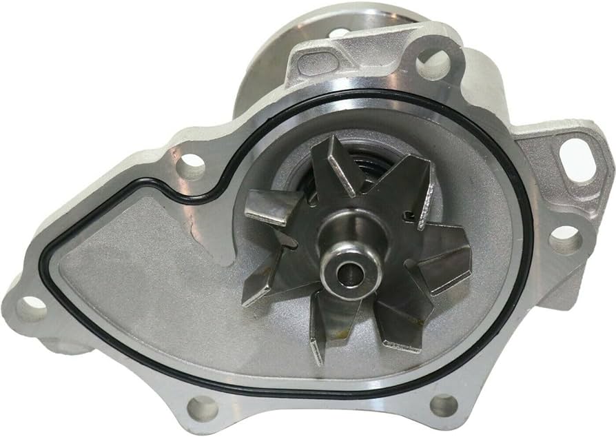
Water pump is the heat of the cooling system which pumps the coolant it consists of an impeller a pulley flange and an O – ring the impeller is driven by the engine drive belt through a pulley
Radiator


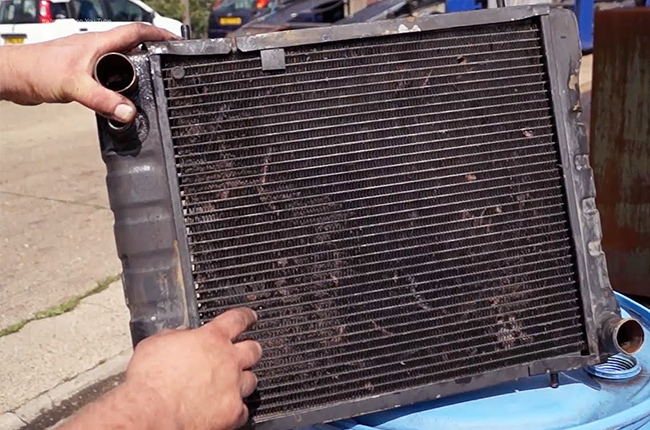
The radiator is a heat exchanger used to transfer the excess heat developed by engine to the atmosphere the radiator having an inlet port outlet port, a drain plug and a radiator pressure cap the radiator pressure cap plays a vital role in the cooling system
Thermostat


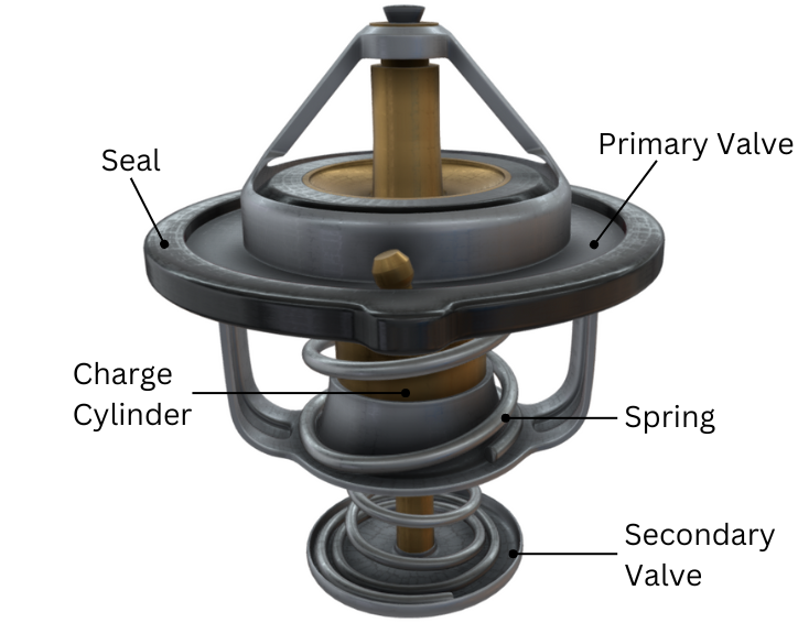
The thermostat is a valve which regulates the flow of a coolant and helps to maintain the proper operating temperature for the engine the thermostat consist of a frame, charge cylinder main valve ,main spring bypass valve and secondary spring
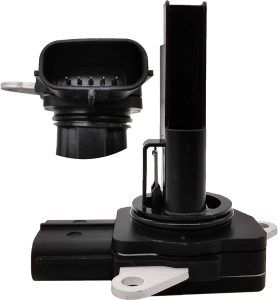
Coolant temperature sensor (CTS)


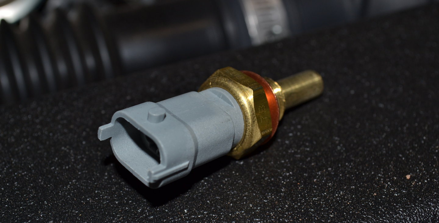
It is used to monitor the engine temperature the ECU will use this data to manage fuel injection and ignition time some engines have more than one coolant temperature sensor the data is also used to control the radiator fan and to update the temperature gauge on the driver console it consists of a sensing probe and an electrical connector most coolant temperature sensors are the negative temperature coefficient type which means the temp increases the resistance will decreases the CTS is a can be two pin type or a three pin type depending on the make of vehicles
Working
How these part working together ?
Pistons are contained inside the engine block in which each of them will function above the engine block comes the head gasket which provides sealing between engine block and engine head It avoids compression leaks and oil or coolant leaks into the cylinder above that comes the engine head the engine having a safe passage through which the coolant can flow without entering into the cylinder or mixing up the with the oil this pessage is known as water jacket
Let’s put the part one by one and how it’s works
The water pumps the coolant throughout the system with the help of radial impeller it’s driven by engine itself using a serpentine belt the serpentine belt also drives the power steering pump, alternator ,AC compressor but for now only water pump shown now the connections the thermostat bypass hose ,the thermostat housing inside the thermostat the radiator and the radiator fan the lower radiator hose the water pump outlet hose the upper radiator hose the coolant expansion tang expansion bleed hose coolant overflow hose so finally let’s get into the working starting with the thermostat the thermostat is actually a valve which regulates the flow of the coolant it will always be covered in the coolant so that the temperature can be sensed let’s start the operation from a cold engine when the engine is cold the bypass valve stays open so the coolant bypasses the radiator and recirculates through the engine this helps the engine to heat up to the operating temperature quickly eventually the coolant temperature increases by absorbing the heat from the engine .once the coolant starts to reach higher temperature which is usually between 160 to 190fahrenheit  the bypass valve will start to close and main valve will start to open this allows the cold coolant from radiator flow to the engine side and the hot coolant from engine side to the radiator in most cars the coolant temperature sensor is located near the thermostat housing it will turn on the radiator fan of the coolant to the radiator side at high temperature now the hot coolant in the radiator will release its heat to the atmosphere with the help of the fan at the same time the cold coolant received from the radiator will start to absorb the heat from the engine for the next cycle heating liquid inside a closed system always builds up the pressure
How to maintains the pressure ?
The role of radiator pressure cap it consists of a spring loaded valve mechanism which will respond to higher pressure reaching a pressure about 15psi will push the pressure cap valve and the coolant flows the expansion tank until the pressure goes down to operation level and when systems cools down the vacuum inside the system sucks back the coolant from expansion tank in case if there is to much pressure build up in the system due to trapped air or other failures the coolant in the expansion tank will be pushed out through the overflow hose
Heater system
The car heater system is a part of the engine cooling system the heater system consists of the heater core, inlet and outlet hose a heater control valve which is optional and cannot be found in all vehicles the heater core act as a radiator dissipating heat from the hot coolant to the vehicle interior using a blower pump,alternator,AC .
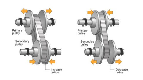
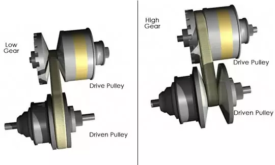
Intro: Continuous variable transmission which ensures a smooth driving experience it provides a infinite number of gear ratios making gear change operation
an unnoticeable experience : https://amzn.to/49PNf24


Inner working of CVT including reverse gear ?
Two conical pulleys and a steel belt makeup a basic CVT the input pulley turns the belt and the belt turns output pulley the gap between the cones determined
the effectiveness diameters of the pulleys for this configuration the output speed will be less than

input speed
Under drive
Doubt >Din
As gaps decreases the effective diameter of the pulley increases that’s the simple mechanism of basic operation of CVT
Now we see what happens to the arrangement when right side cone of the input is moved to the right and left cone of output is moved to the right
the gaps are reverse of previous case this means the effective diameter of pulley is also reverse and hence we will get an overdrive the transmission
control unit will adjust the width between these cones as a result any other kind of transmission the speed change will smooth and unnoticeable
How a reverse gear is even possible with this mechanism :::::
In order to achieve forward and reverse gear ratios planetary set arrangements is used in CVT first look at gear mechanism then move to reverse gear the
input shaft connected to sun gear carrier or planetary set is fitted with the input pulley this means the output of planetary set is drawn from carrier if ring
gear is also turned at the input speed the carrier will rotate at input speed as well this possible by connecting the sun gear with ring gear a clutch pack used for
this purpose if clutch pack is well pressed the frictional force between the plates will lock the sun gear to the ring gear this how forward gear is achieved whole
mechanism is moves as single unit now keep the gear stationary with second clutch pack the result is quite different the stationary ring gear will force the output
carrier to turn in reverse direction so does the input pulley to achieve reverse just released the first clutch and engage the second clutch the CVT offers a variety of
gear ratios for the reverse gear also even though it is not programmed to do so.
Advantages


Strapless transmission
Smooth drive
Better fuel
Consumption
Good adaptability
Disadvantages
High cost
Unlimited amount of torque
High wear

Introduction:::

https://amzn.to/3W3uRPO
the basic function of both is to deliver air in internal combustion process the main distinction between the two superchargers are mechanically powered often by connection to engine crick shaft while turbos are powered by exhaust gas
How superchargers work?

https://amzn.to/4b0dhR1
The supercharger sit on top of air intake manifold certain time belt transfer crack shaft power to supercharger pulley pulley diameter and construction is easily accessible way to quickly alter super charger performance characteristics and give your drive system deliver incoming power system to imposing rotors the outside air enter into airlifter and intake pipe the interlocking rotors force air through the supercharger the long fins or ridges that expand the length of router shaft or lobes the air exit the supercharger through a specially shaped discharged put at bottom of housing
Common supercharger types :
1 Roots
it’s basic function is as a air blower as post other designed that compress air
2 Twin screw
it’s featured with common complex routers with internally designed lobes that compressed air as moved through the unit this increased complexity result in better performance and but also higher manufacturing cost
3 Centrifugal
is have much common with turbo design concept they are still mechanically driven they produce an exponential power curve and after tune to make fore boost engine redline
How turbos charger work ?


turbo connects to engine exhaust system the exhaust manifold may b specially designed for turbo placement and to handle increase heat and pressure the turbo has two separate compartments
1 turbine sections
2 compressor sections
exhaust flows to the turbine sections as a exhaust heat and pressure drive the turbine and exhaust wheel the shield shaft connects the exhaust wheel to the compressor wheel the compressor wheel pulls air into the air filter and intake pipes it specially shaped fins force air through a increasing smaller chambers building compression the air get hot during an intake and compression so most turbo setup have an intercooler between turbo and engine intake to get air back down in ambiance temperature cooler air has much more density serving the goal of forcing more air into the engine the intercooler work something like a radiators plugged air passes through internal tubes as outside air rushing outside by cooling
here are common turbo design
single turbo shown here
where all exhaust flows through a single turbo charger
twin turbo
a setup with two turbo charger
twin scroll turbo
exhaust exit the cylinder in a pose with high pressure section follow by low pressure it separates the cylinder in pairs so the exhaust pulls ways don’t interfere into each. other and continous streams of maximum pressure exhaust reaches the turbine
General comparison
they both have common general term
super charger are powered by mechanically energy e.g by connection to engine crink shaft
while turbo are powered by otherwise wasted heat energy from engine exhaust
Boost characteristics
roots and twin screw charger they have positive displacement means they move at same amount of air for each engine revolution
regardless of rpm this also means they can make boost immediately even at low rpm have a fairly minimal power curve
turbo set up produce exponential power curve
since they are powered by exhaust turbo takes time to build turbine speed in pressure before producing usable boost this delay is called turbo lag
Efficiency
supercharger take power to make power have average setup acquire 40-60horse power
function this does not mean that overall engine efficiency is always sacrifice and some setup increase fuel economy when not driven aggressively
turbo do increase back pressure on the engine they drive power primarily as such they can be very efficient

conclusion
super charger can be less complex less expensive way to increase engine performance they can easily be maintained
they can be ideal in a application acquired predictable boost at all rpm

turbo might

In this topic today i will talk about knock sensor .
what is knock sensor ? also we will learned about knocking.
What is difference between knocking and pre-ignition and also know the reason of knocking in the engine and how we fix these problems .

Now lets start the topic…

1 : LOCATION ?
First we talk about knock sensor location ,The knock sensor is located on the outside of the engine block.

2 : WORKS ?

As its sensor name is knock sensor It is intended to record knocking noise in all engine operating states in order to prevent engine damage.
so the works of knock sensor is to trace the bad vibration in the engine its mean knocking , exactly what is knocking Normal condition 4 cylinder or 4 storks engine leads piston downwards
in the first stroke or intake stork and air plus fuel entered the cylinder second stroke piston takes air fuel mixture compressors intake up
then spark plug comes out at the top up the piston and the power stroke piton goes down again filled the burn gases in the cylinder 4th storks
exerts in which piston burns the gases take them out ,this is normally functions on engine.
where is knocking these all storks let we know normal condition fuel and air mixture proper burring and the mixture is burning improper we called that is knocking.

3 :PRE_IGNATION ?
its mean before time ignited or burn , when the piston fast or slow comes up while compressing air and fuel mixture so on the way mixture burn that’s called PRE _ IGNATION.
means before spark comes out the mixture burns.

4: THERE ARE TOW RESONS OF PRE-IGNATION ?

when hot carbon particles entered the chamber from the valves the fuel burns before its life.
bad spark plugs or low quality spark plugs gets too hot its burns before fuel ignition.

5: EFFECTS OF KNOCKING ON THE ENGINE ?

Due to knocking or pre-ignition or improper movement of piston and valve will be damage of engine cylinder and pistons.
basically knock sensor designed to protect functional engine condition to produce high or low fuel consumption.
if comes out knocking the knock sensor is controlled mixture by looking ecu signal.

When this code comes, it means that the catalytic of the vehicle is
low response and why does it the low response that catalytic is dirty.
Catalytic must be washed with a cleaner after every 30,000 km drive if you cannot wash it with a cleaner.

In the catalytic, the exhaust of the engine is stored and the oxygen sensor gases are collected, which are being told to the computer
by sensing the oxygen sense And adjusts the fuel mileage by injecting that accordingly with the computer injector
.

The location of the catalytic is either in the middle of your exhaust or is placed on the front, inside which there is a soil damp .

For this first of all you have to try to wash your catalytic if even after that your issue is not solved then change the oxygen sensor.
Check the exhaust is leaking from anywhere and after that in the there is catalytic damage from inside So fix it on the and then check your code will also be clear of p0420
.

Toyota Corolla Fuel Consumption & Computerized Tuning In 2024.

Today we will talk about how to set the tuning and fuel average of Toyota Gli.

1 Spark Plugs. 

Toyota uses more Denso plugs, if any other company’s plug is used in a Toyota car, then the car may consume more fuel.

The gap in most plugs is approx.6mm if the gap is less or more then the pickup of the car may be less or the car may be missing.

Denso iridium plugs have life of 40000k/m but some people do not realize this and not change the plugs Due to which the plug is not
able to give its performance and the car gets disturbed.

2. Spark Coil

The coils are important as the plugs. If the current in the coils becomes weak then the engine fuel will be wasted And the car started misfiring due to which the car took more accelerator and the injector started injecting more fuel.

3. Injectors

The job of the injector is to supply fuel evenly to the engine If there is debris in the injectors or the injectors leak, the engine will get enough fuel and the car will smoke black and the pickup will be reduced, And sometimes the car may give code of system to lean or system to rich

4. Feul Motor.

The main function of the fuel motor is to supply fuel from the tank to the injector. Required fuel pressure can vary depending on your vehicle’s engine and fuel system. while modern multipoint fuel injected high-performance engines can require as much as (60 PSI) and it is necessary to have a pressure of at least( 45 psi.)

5. Feul Filtter

If the fuel filter is clean then the fuel will get proper supply of motor fuel and the car will pick up as much fuel as the engine requires the injectors will spray it the remaining fuel will go back into the tank.

6.Airflow Sensor.

The function of the airflow sensor is to send equal amounts of fuel and air to the engine. If the airflow sensor is weak then sometimes too much air and sometimes too much fuel leaks into the engine but the engine does not check. Due to this, the of the vehicle reduces and many times the car takes not the accelerator. 

Note . If the sensor gets damaged then the check engine light goes on and the car starts having trouble starting and starts smoking black smoke.

7.O2 Sensor ( Oxygen )

What is the purpose of oxygen sensor the of checking the exhaust that comes out of the engine If the amount of either exceeds the air or fuel supply in the exhaust, one of the oxygen sensors will be alerted ecu and an attempt will be made to adjust to the problem.

In case of faulty oxygen sensor, the accelerator stopped and the pick was used in the car sieve and may have started giving black smoke.

The basic function of the TP sensor is that it tells the reading
Ecm whether the throttle is open ecm reduce the amount of air and fuel to equalize in the engine.

1,location:
The Location of the tp sensor is on the back and front side of the throttle.

2,Works:
Tells the air ratio to the computer when the vehicle is parked or drive.

3,symptoms of A Bad Tp Sensor:
First of all the checking light came on & genrate Few dtc p0122 , p0123, p0124 and p2135.

4,Weak acceleration.
When ecu is not getting data So more amountof air and less amount of petrol
got mixed in the engine.

5,engine Rough Idling:
When the tp sensor is damaged or weak So in the speed of 600 to 900 rpm
the up and down keep happening.

6,Excess Fuel consumption:
Ecu gets wrong signal due to bad throtel sensor,
Because of which the amount of air and fuel in the engine is not equal
and car gives poor black smoke or smells of petrol and the car may take longer starting.

7.Acceleration changes:
Sometimes the car doesn’t take the whole race And sometimes car would race herself than necessary.